Through-Silicon Via
TSV Fabrication
At Nanosystems JP Inc., we offer a complete 5-step TSV fabrication flow, DRIE Bosch etching at >50:1 aspect ratio, PECVD SiO₂ dielectric liner, ALD Al₂O₃ for conformal thin liners, TiN/Ta barrier and Cu seed by sputtering, void-free Cu electroplating, and CMP endpoint control. For 3D-IC memory stacking, 2.5D silicon interposers, and MEMS-on-CMOS integration.
Thick substrates: through-silicon vias in silicon up to about 1.5 mm thick (double-sided DRIE, Cu fill verified by X-ray CT) are offered as a development engagement. Thick-substrate TSV →
(depth-to-width)
through-wafer
end-to-end
SEM-verified
TSV, the vertical wire
inside the chip stack
Through-Silicon Vias are copper-filled vertical channels etched through the full silicon wafer thickness, providing electrical signal and power connections between stacked die layers in 3D-IC packages. Without TSV, dies in a stack must communicate via slow, power-hungry wire bonds around the edge of the stack. TSV enables the bandwidth density of HBM memory and the compact form factor of advanced sensor stacks.
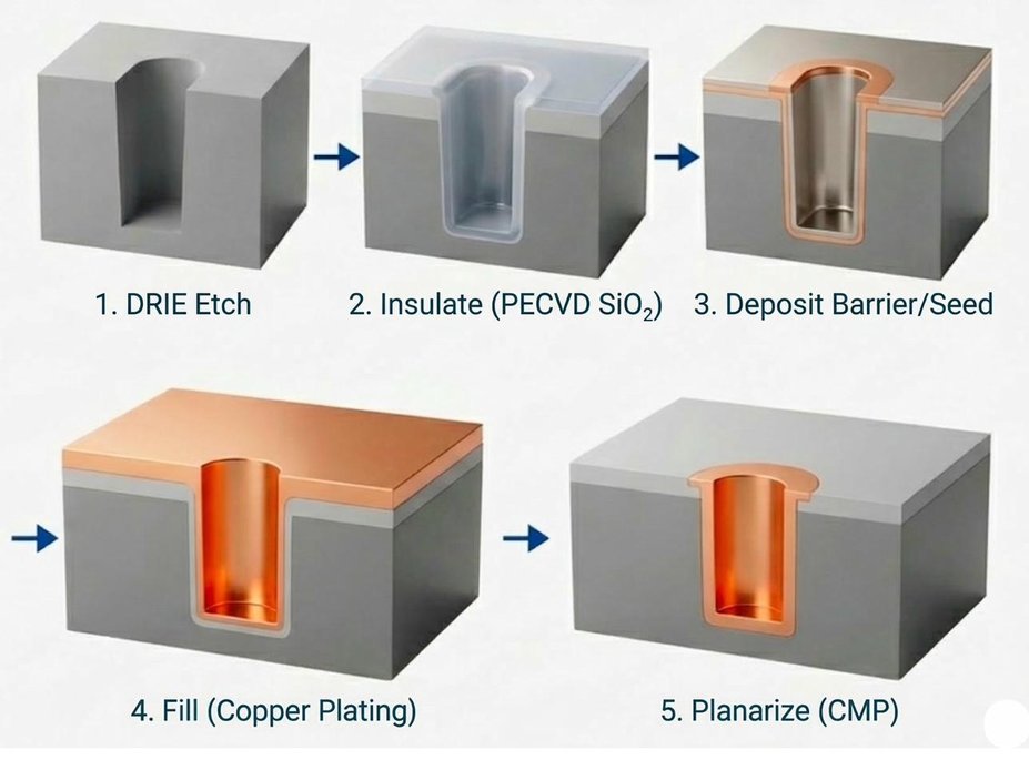
From silicon surface
to planarized copper vias
At Nanosystems JP Inc., every step of the TSV flow, etching, lining, barrier, plating, and polishing, is managed as one program by a dedicated project manager.
High Aspect Ratio DRIE Etch
The DRIE Bosch process alternates between SF₆ plasma etch cycles (isotropic silicon removal) and C₄F₈ passivation cycles (depositing a fluoropolymer layer on sidewalls), producing near-vertical sidewalls with controlled Bosch scalloping below 100nm amplitude. Silicon etches with >100:1 selectivity to the SiO₂ hard mask, enabling deep vias (over 100 µm) without mask erosion. Etch uniformity across the wafer is monitored by laser interferometry or optical emission spectroscopy for endpoint detection. Via diameter, depth, and sidewall angle are measured by cross-section SEM on monitor wafers before production lots proceed.
Dielectric Liner Deposition
The exposed silicon sidewall and bottom are electrically isolated by a conformal dielectric layer. PECVD SiO₂ (PE-TEOS) is deposited at temperatures below 400°C to protect front-side devices, providing high step coverage into the deep via geometry. The dielectric must cover the complete via sidewall without pinholes or thinning at the corners, as any bare silicon exposure would create a leakage path. For vias requiring thinner, more conformal liners (narrow pitch or high-density TSV arrays), ALD Al₂O₃ provides angstrom-level thickness control and near-100% step coverage. The liner thickness is confirmed by cross-section TEM or ellipsometry on monitor wafers.
Barrier & Seed Layer Deposition
Copper diffuses rapidly in silicon, even at room temperature, and degrades devices if it reaches the active region. A diffusion barrier is mandatory: TiN, Ta, TiW, or Ti is sputtered over the dielectric liner at conformal coverage into the via geometry. Immediately after the barrier, a thin Cu seed layer is sputtered, providing the electrically conductive nucleation surface needed for electroplating to initiate uniformly across the via bottom and sidewalls. Both barrier and seed layers require step coverage down the full via depth, even at >50:1 aspect ratios, achieved by ionized PVD (iPVD) or collimated sputtering conditions. Sheet resistance of the seed layer is measured by 4-point probe before plating.
Void-Free Cu Electroplating & Anneal
Copper electroplating using bottom-up superfill chemistry, a combination of accelerator, suppressor, and leveler additives in the electrolyte, preferentially deposits Cu from the bottom of the via upward, preventing the void formation that would result from top-down fill. The plating current density is carefully controlled to avoid Cu mounds or dimples at the via center. After plating, wafers are annealed at approximately 400°C under N₂ atmosphere, this drives Cu grain growth and relieves the residual stress from plating, significantly reducing wafer bow. Void-free fill is confirmed by cross-section SEM on representative vias across the wafer diameter before proceeding to CMP.
CMP, Endpoint-Controlled Planarization
Cu CMP removes the electroplated overburden and planarizes the wafer surface, stopping on the barrier layer using in-situ eddy-current endpoint detection on the Cu overburden, or optical endpoint by reflectometry. The barrier layer is then cleared by a brief over-polish or second CMP step. The final surface presents Cu via tops flush with the surrounding SiO₂ or barrier, with a topography step of less than 5nm, ready for RDL dielectric deposition or direct wafer bonding. Post-CMP metrology: wafer bow (warpage), within-wafer Cu dishing, SiO₂ erosion, and surface roughness (Ra) are measured and reported in the process data sheet delivered to the customer.
TSV in the advanced packaging stack
TSV fabrication is never the only step. It fits into a larger flow, preceded by wafer-level device processing and followed by reveal, RDL, and bumping. All these steps are available as a single program.
Via-first, via-middle,
or via-last, we support all three
At Nanosystems JP Inc., we offer TSV fabrication as a complete program, from DRIE etch through to CMP planarization. Via-first, via-middle, and via-last integration are all supported. The program is managed end-to-end as one project, with direct technical engagement from inquiry through to delivery.
Via-First
TSVs etched and filled before transistor fabrication begins. Enables the highest via density (tightest pitch) because no completed devices constrain the thermal budget. Via-first vias are normally filled with doped polysilicon or tungsten rather than copper, because the fill must survive the full front-end thermal sequence.
Via-Middle
TSVs fabricated after the transistors but before the metal interconnect layers. The most common approach for memory dies and mixed-signal ICs. Thermal budget is constrained by completed transistors, TSV anneal typically limited to 400°C.
Via-Last
TSVs etched and filled after all BEOL metal layers are complete. Maximum design flexibility, via position not constrained by front-end layout. Thermal budget most constrained (<300°C) due to completed Cu BEOL. Most common for interposer and MEMS-on-CMOS.
Complete TSV fabrication
specifications
| Parameter | Specification / Range | Notes |
|---|---|---|
| Via Etch Method | DRIE, Bosch process | SF₆/C₄F₈ alternating cycles |
| Aspect Ratio (depth:width) | >50:1 | Depth >100µm, width from ~3µm |
| Via Depth | 100 µm and deeper | Through-wafer or blind via |
| Sidewall Angle | 89-90° (near vertical) | Bosch scalloping <100nm amplitude |
| Hard Mask | SiO₂ | Si:SiO₂ selectivity >100:1 |
| Dielectric Liner, Standard | PECVD SiO₂ (PE-TEOS) | High step coverage, <400°C |
| Dielectric Liner, Conformal | ALD Al₂O₃ | Near-100% step coverage, narrow vias |
| Diffusion Barrier | TiN, Ta, TiW, Ti | Prevents Cu diffusion into Si/oxide |
| Cu Seed Layer | Sputter PVD | Ionized PVD / collimated for deep vias |
| Cu Fill Method | Electroplating, superfill | Bottom-up fill, additive chemistry |
| Fill Quality | Void-free | Confirmed by cross-section SEM |
| Post-Plate Anneal | ~400°C, N₂ atmosphere | Grain stabilization, stress relief |
| CMP Endpoint | Eddy current / optical | Stops on barrier layer |
| Post-CMP Topography | <5nm step height | Dishing and erosion measured |
| Wafer Size | 2 inch to 12 inch (300mm) | All standard wafer diameters |
| Via Integration Timing | Via-first, via-middle, via-last | Process flow dependent |
Where TSV is being used today
3D-IC HBM Memory Stacking
High-bandwidth memory (HBM) uses TSV arrays to connect stacked DRAM layers to each other and to the logic die beneath. Each HBM2/HBM3 die contains thousands of TSVs at fine pitch. The bandwidth increase over conventional DRAM is directly enabled by the parallel via array, something bond wires cannot achieve.
2.5D Silicon Interposer
A silicon interposer die contains a TSV array connecting chiplets on the front surface to C4 solder bumps on the back. The interposer routes signals between CPU, HBM, and I/O chiplets at much finer pitch than an organic package substrate, enabling chiplet integration for HPC and AI accelerator packages.
MEMS-on-CMOS Integration
MEMS inertial sensors (accelerometers, gyroscopes) stacked face-to-face on CMOS readout dies using TSV for vertical signal routing. Eliminates bond-wire parasitic inductance and resistance, which matters for high-bandwidth sensor readout. Enables the compact form factor needed for IMUs in drones, AR/VR headsets, and autonomous vehicles.
Silicon Photonics Interposer
Silicon photonics interposers for co-packaged optics use TSVs to route electrical signals from the electronic IC to the photonic IC, and from both to the package substrate. TSV provides the electrical feedthrough while optical signals travel in-plane through waveguides. Critical for 800G/1.6T optical transceivers.
Backside Illuminated Image Sensors
BSI image sensors use TSVs to connect the front-side CMOS readout circuit to the backside-illuminated pixel array, and then to the package substrate. The TSV enables a compact BSI architecture without wire bonds around the die edge. Applied in smartphone cameras, scientific sensors, and LiDAR receivers.
RF Coaxial TSV Structures
Coaxial TSV structures for RF MEMS and millimeter-wave packaging, a central signal via surrounded by grounded shield vias, providing high-isolation RF signal routing through the silicon substrate. Applied in 5G/6G front-end module integration and mmWave radar chips for automotive ADAS.
What makes Nanosystems JP Inc. TSV capability
different
All 5 steps under one project, no re-quoting, no delays
DRIE etch, PECVD/ALD liner, barrier/seed sputtering, Cu electroplating, and CMP are quoted, scheduled, and reported as one project, managed end to end by a dedicated project manager.
>50:1 aspect ratio
A >50:1 aspect ratio enables through-wafer TSVs in thicker substrates without requiring extreme wafer thinning, reducing process complexity and wafer fragility in thin-wafer handling.
Void-free fill confirmed by SEM before CMP
Every production lot includes SEM cross-section inspection of representative vias after plating, before the wafer proceeds to CMP. Voids caught at this stage save the cost of CMP, TSV reveal, RDL, and bumping steps on a defective wafer.
TSV + reveal + RDL coordinated in one project
TSV fabrication is rarely the final step, it is followed by TSV reveal (backgrinding + etch + passivation + CMP) and then RDL and bumping. All three phases are available and managed as one project, with one quotation and one schedule.
Via-first, via-middle, and via-last all supported
We handle all three TSV integration timing approaches, matching our process conditions to the thermal budget available at each stage of your device flow. Via-last at <300°C for completed BEOL wafers (including the post-plate anneal); via-middle at <400°C for post-transistor wafers; via-first at higher temperatures for blank substrates.
From 1 wafer prototype, no minimum lot size
Run a single engineering wafer to optimize via depth, fill quality, liner integrity, and CMP endpoint before committing to a full production lot. The same process recipe carries into repeat production on an established baseline; your prototype data is that baseline.
Building an AI or HPC
interposer?
Our complete 2.5D/3D interposer packaging flow covers TSV, TGV, RDL, and hybrid bonding - all managed as one project by a dedicated project manager at Nanosystems JP Inc.
Start your project.
Initial response within one business day.
Share your process requirements, substrate, and production volume. A Nanosystems JP Inc. engineer will give an initial response within one business day. Full quote typically within 7-10 business days, subject to project complexity and NDA requirements.