RDL, Redistribution
Layer Fabrication
At Nanosystems JP Inc., we offer two complete RDL routes, polymer passivation (BCB, PBO, PI) and Cu damascene, for redistributing chip I/O from device pad pitch to package bump pitch, enabling fan-in and fan-out wafer-level packaging. Both routes are available as standalone processes or as part of a full TSV → RDL → UBM → C4 bumping flow, with integrated backgrinding, dicing, and flip-chip assembly.
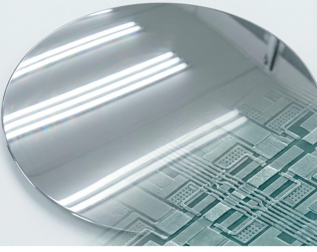
polymer & Cu damascene
BCB · PBO · PI · Acrylic
Cu damascene RDL
both supported
Rerouting chip I/O from
pad pitch to bump pitch
Device pads on a finished wafer are typically at a pitch of 50 to 150 µm, too tight for direct solder bumping at board assembly. RDL fabricates one or more layers of metal interconnect on top of the completed wafer to reroute these pads to a wider, solderable bump pitch, or to extend the I/O footprint beyond the die edge entirely (fan-out).
What RDL Reroutes
After TSV reveal CMP, the wafer has clean Cu contacts flush with the dielectric. RDL takes these contacts, at via pitch, which may be 5 to 50 µm, and fans them out to a C4 bump pitch of 100 to 200 µm. The RDL metal layer is the only electrical connection between the TSV and the solder bump: its resistance, inductance, and layout directly affect device performance.
Choosing a Route
The two RDL routes, polymer passivation and Cu damascene, make different trade-offs. Polymer passivation is lower cost and lower temperature; Cu damascene achieves finer line/space for high-density applications; line resistance follows the conductor cross-section and metal, so it is confirmed per design rather than by route. The dielectric choice within polymer passivation (BCB, PBO, polyimide, or acrylic) further affects dielectric constant, cure temperature, and chemical compatibility.
Coordinated After TSV Reveal
RDL always follows TSV reveal or wafer-level pad preparation. When run in the same project, RDL lithography is scheduled directly after CMP while the Cu contact surface is fresh and oxide-free. A common yield loss in fragmented RDL flows is Cu surface contamination that accumulates during storage between separately ordered process steps.
Polymer passivation vs
Cu damascene, side by side
Both routes are available. Our engineers recommend the optimal route based on your required line/space density, dielectric loss target, temperature budget, and cost.
Polymer Passivation RDL
An organic dielectric layer is spin-coated, patterned by photolithography, and cured, forming the interlayer dielectric between metal RDL layers. Cu or Al metallization is then deposited and patterned on top. The polymer planarizes the underlying topography naturally, simplifying subsequent lithography. Typical cure temperatures of 200 to 350 °C keep the process compatible with completed CMOS devices. The main trade-off versus damascene is line/space density: our polymer RDL design window is typically 5 to 10 µm lines, whereas our damascene route reaches sub-2 µm; finer polymer routes exist elsewhere and are not offered here.
Cu Damascene RDL
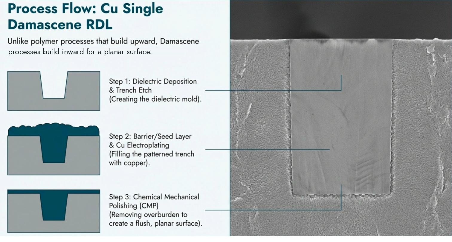
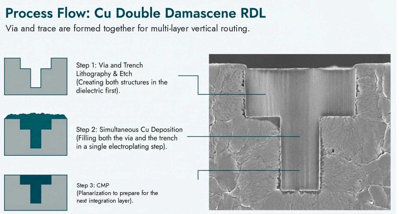
Trenches and vias are patterned into a dielectric (typically SiO₂ or low-k CVD dielectric) and then filled with Cu by electroplating, the same process as advanced CMOS BEOL interconnects. CMP planarizes each layer. The inlaid Cu process eliminates the etch step on patterned Cu, enabling much finer line/space than polymer RDL while achieving lower line resistance at equal geometry due to the pure Cu fill with a barrier and seed stack selected for the dielectric and geometry. Dual damascene forms via and trench in a single Cu fill + CMP step, reducing process steps for multi-layer RDL.
Four passivation materials BCB, PBO, Polyimide, Acrylic
The polymer dielectric choice determines the dielectric constant, cure temperature, chemical resistance, and application suitability of the RDL layer. Each material occupies a specific niche, our engineers advise based on your device requirements.
Single and dual damascene for fine-pitch multi-layer RDL
Cu damascene RDL uses the same principles as advanced CMOS BEOL, Cu inlaid into dielectric trenches and planarized by CMP, enabling the finest line/space achievable at wafer scale.
Dielectric Deposition
A CVD silicon dioxide or low-k dielectric is deposited conformally over the wafer surface, over the TSV contacts or device pads. The dielectric thickness determines the final Cu line height. For multi-layer RDL, each layer repeats this step on the CMP-planarized surface of the previous layer. Low-k CVD dielectrics (SiOCH or porous SiO₂) reduce RC delay in fine-pitch signal lines, important for RF and high-speed digital RDL applications above 10 GHz.
Trench & Via Lithography + Etch
In single damascene, via openings and metal trenches are patterned and etched in two separate lithography + etch steps. In dual damascene, vias and trenches are formed in the dielectric and filled in a common metallization sequence, followed by CMP; the patterning sequence depends on the integration scheme. The via connects to the layer below; the trench defines the horizontal wire geometry. After etching, photoresist is stripped and the dielectric surface is cleaned.
Barrier & Seed Layer Deposition
A thin Ta or TaN diffusion barrier is sputtered conformally into the etched trenches and vias, preventing Cu from diffusing into the surrounding dielectric. A Cu seed layer immediately follows. For fine-pitch damascene RDL, both barrier and seed must achieve step coverage into sub-5 µm-wide trenches, requiring ionized PVD or atomic layer deposition (ALD) barrier processes. The seed layer thickness and conformality directly determine the uniformity of the subsequent electroplating fill.
Cu Electroplating
Copper is electroplated to overfill the trenches and vias, the Cu overburden must fill the trench completely with no voids before the CMP step can planarize. Superfill additive chemistry (accelerator, suppressor, leveler) drives bottom-up fill into the narrowest trenches, preventing seam voids that would create high-resistance line segments. Cu overburden thickness is controlled to minimize CMP removal time while ensuring complete fill. Post-plate inspection by optical microscopy checks the surface condition before CMP; internal fill is verified by the agreed cross-section or other qualified method and sampling plan.
Cu CMP, Planarization
CMP removes the Cu overburden and barrier layer, stopping at the dielectric surface and leaving Cu inlaid only within the trenches and vias. Endpoint detection by eddy current on the Cu ensures uniform stop-on-dielectric across the wafer. Post-CMP metrology: Cu recess (dishing within wide lines), dielectric erosion, and within-wafer uniformity are measured and reported. The planarized surface is the base for the next RDL dielectric layer in multi-layer RDL, or for direct UBM and bumping in single-layer designs.
Fan-in WLCSP and FOWLP both available
RDL is the enabling technology for both packaging architectures. The choice between fan-in and fan-out depends on the I/O count relative to die area, and the required package footprint.
Fan-In WLCSP
RDL redistributes bond pads from the chip's native pitch to a wider solderable ball pitch, entirely within the die footprint. No mold compound, no interposer. The package is the same size as the die. One or two RDL layers are typically sufficient. The smallest possible package form factor, ideal for mobile SoCs, MEMS sensors, RF chips, and IoT devices where PCB area is at a premium.
Polymer passivation RDL (BCB or PBO) is the standard route for WLCSP, low-k dielectric reduces RF parasitic coupling between adjacent signal lines, and cure temperatures below 300 °C are compatible with completed CMOS.
Fan-Out FOWLP
Fan-out RDL extends I/O beyond the die edge into a mold compound area, enabling chips with more I/O than the die area can accommodate, and allowing multiple dies to be integrated side-by-side in a single package (eWLB, InFO, and similar approaches). The die is embedded in mold compound, reconstituted into a panel or wafer, and RDL is then fabricated across both the die and mold areas.
Multi-layer RDL (2-5 layers) is typical for fan-out because signals must be routed over a longer lateral distance. PBO is commonly used in fan-out due to its combination of low-k, photosensitivity, and high-volume process maturity. Fan-out enables chiplet integration at wafer scale.
Complete RDL fabrication
parameters
| Parameter | Polymer Passivation RDL | Cu Damascene RDL |
|---|---|---|
| Dielectric Materials | BCB, PBO, Polyimide, Acrylic | CVD SiO₂, low-k CVD (SiOCH) |
| Minimum Line/Space | ~5 µm / 5 µm | <2 µm / 2 µm |
| Dielectric Constant (k) | BCB: 2.65 · PBO: 2.9 · PI: 3.2-3.5 | SiO₂: 3.9 · Low-k: 2.5-3.2 |
| Cure / Deposition Temp | 150 to 350 °C (polymer dependent) | CVD: 200 to 400 °C |
| Metal Layers | 1-4 layers | 1-6 layers |
| Metal Material | Cu (electroplated) or Al (PVD) | Cu (electroplated, inlaid) |
| Barrier | Ti/TiN or Ta (sputter) | Ta/TaN (sputter or ALD) |
| Via Fill | Cu electroplate | Cu electroplate (superfill) |
| Planarization | Natural (polymer spins flat) | CMP after each layer |
| Patterning | Photolithography (BCB/PBO: photosensitive) | Lithography + dry etch |
| Fan-In / Fan-Out | Both | Both |
| Typical Application | WLCSP, FOWLP, RF fan-out, MEMS | 2.5D interposer, HPC chiplet, fine-pitch |
| Wafer Size | 2 inch to 12 inch | 2 inch to 12 inch |
| UBM Integration | ENIG or ENEPIG | ENIG or ENEPIG |
| Bumping Integration | C4 SnAg | C4 SnAg |
RDL across every segment
of advanced packaging
3D-IC Post-TSV Reveal
RDL immediately after TSV reveal CMP reroutes the exposed via contacts to the C4 bump pitch, directly continuing the packaging flow in the same project. Single RDL layer for low fan-out ratios; multi-layer for high-density interposer applications.
2.5D Chiplet Interposer
Fine-pitch Cu damascene RDL on silicon interposer provides sub-2 µm line/space routing between CPU, HBM, and I/O chiplets. Multi-layer damascene RDL achieves the signal density that organic substrates cannot. The primary application driving Cu damascene RDL technology.
Mobile SoC WLCSP
Fan-in BCB or PBO RDL for application processor and modem chips in smartphones and tablets. Single or dual RDL layer redistributes hundreds of I/O pads to the ball pitch required for direct PCB attach. Low-k BCB minimizes crosstalk at RF frequencies used in 5G modems.
Silicon Photonics Packaging
Low-k BCB or PBO RDL on silicon photonics dies routes high-speed electrical I/O signals from the EIC (electronic IC) alongside optical waveguide ports. Dielectric loss in the RDL at 50+ GHz frequencies makes BCB (k=2.65) the preferred choice over higher-k alternatives.
MEMS Sensor WLCSP
Fan-in polymer RDL for MEMS inertial sensors (accelerometers, gyroscopes, pressure sensors), redistributes MEMS bond pads to ball grid for direct PCB attach in IoT devices, drones, and wearables. Eliminates the wire bond parasitics that degrade high-frequency MEMS performance.
RF Front-End Modules
Fan-out PBO or BCB RDL for GaN/GaAs RF chiplets in 5G/6G front-end modules. Fan-out enables more I/O than the small MMIC die area provides. Low-k dielectric is mandatory, even moderate dielectric loss becomes unacceptable at millimeter-wave frequencies.
Power Device Fan-Out
Polyimide RDL for SiC MOSFET and GaN power transistor fan-out packaging. Polyimide's high post-cure temperature stability (service temperature qualified per grade and application) makes it the preferred dielectric for power RDL where device junction temperatures exceed what BCB or PBO can sustain.
Medical & Implantable Devices
Biocompatible polyimide RDL for implantable neural probes, retinal implants, and ingestible sensor chips. Medical-grade polyimide grades with biocompatibility assessments exist, a consideration that BCB and PBO do not meet. Low-temperature acrylic RDL for sensors with strict thermal constraints.
eWLB / InFO Fan-Out Chiplets
Multi-layer PBO RDL on reconstituted fan-out panels for multi-die integration, two or more chiplets embedded side by side in mold compound with RDL routing signals between them and to the package balls. Enables chiplet integration without a silicon interposer for mid-tier HPC and networking ASICs.
What makes our RDL capability
different
Both routes in one coordinated process flow
Polymer passivation RDL (BCB, PBO, PI, acrylic) and Cu damascene RDL (single and double), both available. No need to qualify a separate process source when your device requires properties that one route alone cannot deliver.
Scheduled directly after TSV reveal
RDL lithography is scheduled directly after reveal CMP clears the Cu contacts, while the surface is oxide-free and clean. A common yield-loss mechanism when RDL is ordered separately is Cu surface oxidation during the days or weeks a wafer waits between the reveal step and the RDL step. Scheduling both in one project removes that wait.
All four polymer dielectrics available
BCB for RF and mmWave, PBO for FOWLP, polyimide for high-temperature and biocompatible, acrylic for lowest cure temperature, our engineers match the dielectric to your device, not the other way around.
Sub-2 µm line/space in Cu damascene
Cu damascene RDL achieving sub-2 µm line/space, the density required for chiplet-to-chiplet routing on 2.5D silicon interposers. For our currently quoted routes, sub-2 µm line/space is addressed through Cu damascene; polymer-RDL design rules are confirmed per program.
RDL → UBM → C4 bumping
After RDL, UBM (ENIG or ENEPIG) and C4 SnAg bumping are performed in the same project, completing the full wafer-level packaging sequence in one continuous flow. The flow from TSV reveal to bumped wafer is coordinated as one process flow, on one schedule.
Fan-in and fan-out, designed to spec
RDL layout is designed to your specific fan-out ratio and target bump pitch, not constrained to a fixed platform product. Whether you need a single-layer fan-in at 5 µm line/space or a 4-layer fan-out damascene RDL for a chiplet interposer, the design is yours.
Start your project.
Initial response typically within one business day.
Share your process requirements, substrate, and production volume. A Nanosystems JP Inc. engineer will give an initial response typically within one business day. Full quote typically within 7-10 business days, subject to project complexity and NDA requirements.