AuSn Bump Services
for Silicon Photonics (PIC)
At Nanosystems JP Inc., we offer wafer-level Gold-Tin (AuSn) bumping via two complementary routes, PVD multi-layer thin film (stacked, co-deposition, or direct alloy target) with lift-off patterning, and AuSn electroplating with tunable composition. Eutectic 80/20 and custom alloys. 4-12 inch wafers and cavity wafers. Fluxless hermetic bonding for photonic flip-chip assembly.
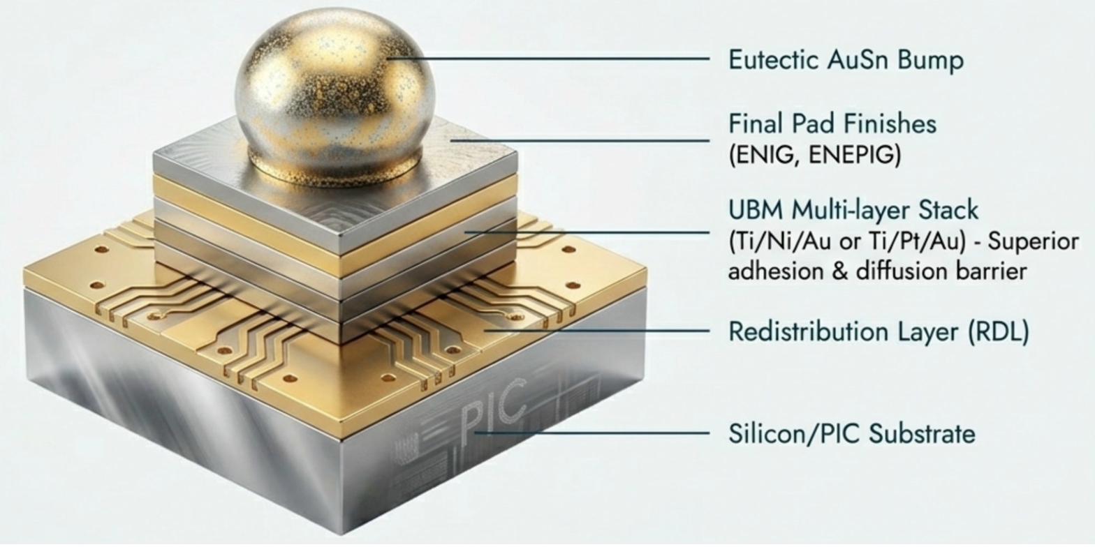
PVD & electroplating
incl. cavity wafers
Au:Sn composition (wt%)
no flux residue
Lift-Off Patterning for AuSn Bumps
PVD multi-layer + lift-off is one of our two AuSn bump fabrication routes. See the dedicated lift-off page for full details on the resist systems, exposure methods, and solvent strip process behind AuSn bump definition.
Wafer-level AuSn bump fabrication
for photonic flip-chip assembly
We fabricate AuSn bumps on your wafer - PVD multi-layer with lift-off, or electroplating - delivering a bumped wafer ready for flip-chip assembly at your facility or chosen assembly site. AuSn is the industry-standard solder for photonic device integration because of three properties that conventional SnAg cannot provide.
Fluxless - No Optical Contamination
Standard flip-chip solders require flux to remove native oxide before bonding, but flux residue near optical waveguide facets scatters light and degrades coupling efficiency. AuSn is bonded fluxless: the gold-rich surface does not form a refractory oxide, and with controlled surface preparation, a protective reflow atmosphere, and the qualified thermal profile, the joint forms without chemical flux. The optical facet stays clean after bonding.
Hermetic - Moisture Barrier
AuSn forms intermetallic compounds (Au₅Sn and AuSn) during reflow that are rigid, high-melting, and impermeable to moisture. This provides a hermetic seal of the kind required for telecom-grade laser packaging, where ppm-level moisture degrades InP laser mirrors over the product life; qualification against a specific standard is performed on the customer's package. The same all-metal, fluxless stack is what makes AuSn UHV-compatible and low outgassing, the die attach of choice inside vacuum cans and cryostats, covered in full on our cryogenic and UHV metallization page.
Self-Aligning - ±1µm Placement
When the solder is molten, AuSn surface tension pulls the die into alignment with the waveguide, correcting pick-and-place errors. For a Si waveguide mode field diameter of 2-3µm, even ±0.5µm lateral misalignment reduces coupling by >3dB. Bumps fabricated to the correct geometry and composition enable ±1µm self-alignment during your assembly reflow.
PVD thin film and electroplating -
matched to your application
Both routes deposit the same eutectic AuSn alloy but use different physics, enabling different trade-offs in composition control, bump height, throughput, and feature resolution. Our engineers recommend the optimal route based on your PIC platform and bump geometry.
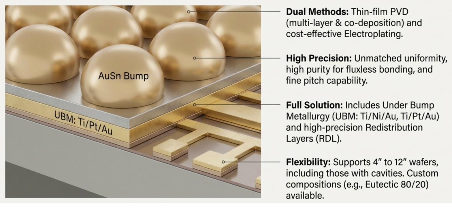
PVD Multi-Layer Thin Film Deposition
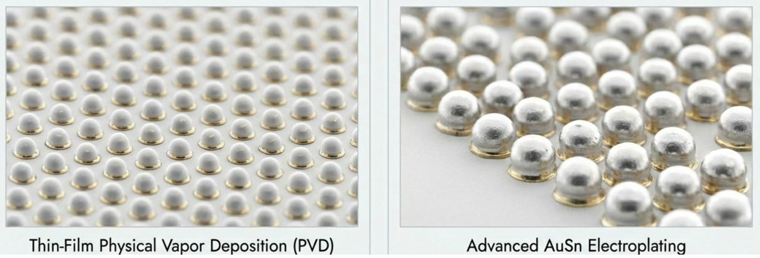
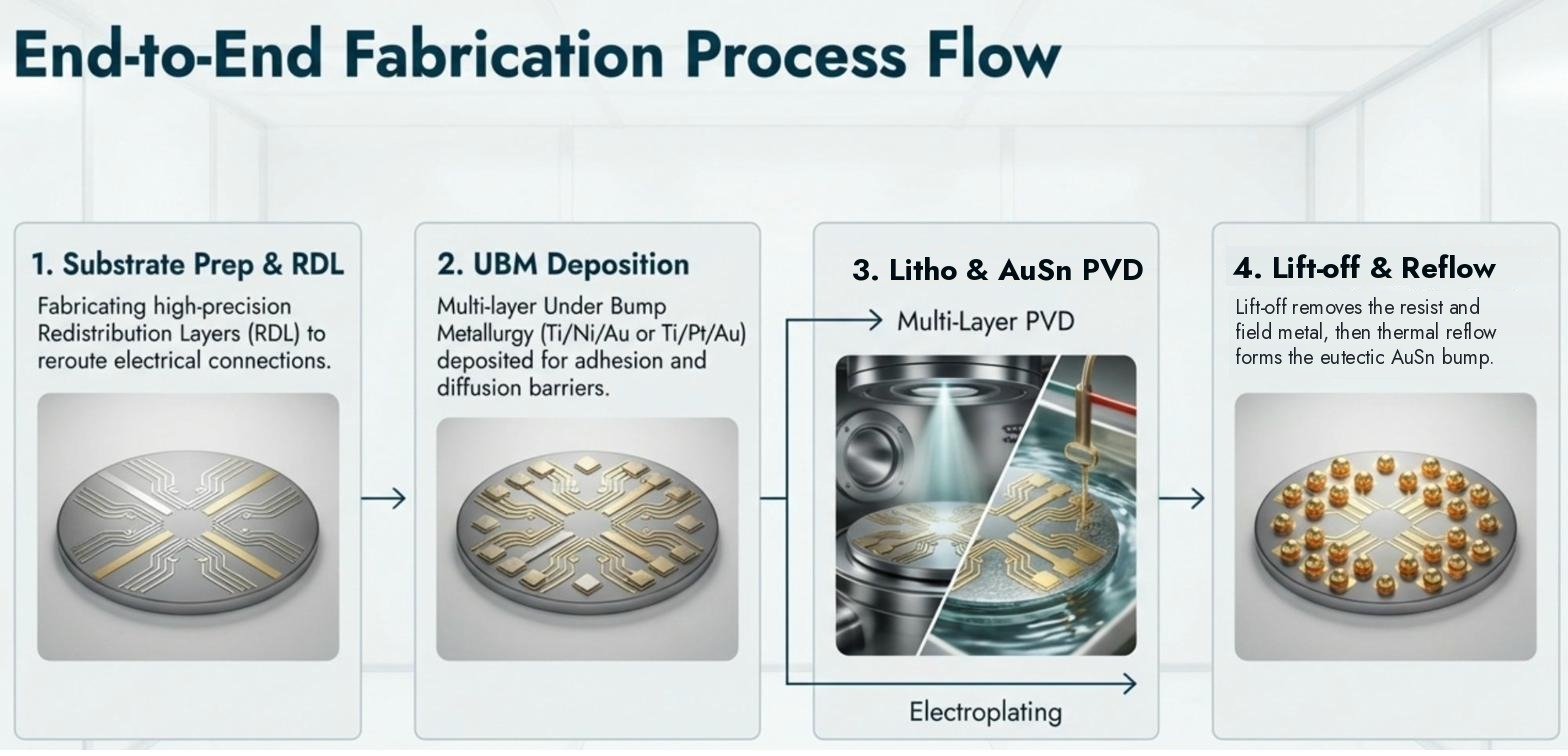
Physical Vapor Deposition (PVD) deposits gold and tin sequentially or simultaneously from sputtering or evaporation targets. The alloy composition is precisely controlled by the relative thickness or deposition rate of each layer. After deposition, lift-off lithography defines the bump pattern with submicron dimensional accuracy, no wet metal etching required. This is the premier route for applications requiring the highest compositional precision and finest feature definition. Alloy compositions including eutectic 80/20, 75/25, 70/30 wt%, and other custom off-eutectic ratios are achievable by adjusting individual layer thicknesses.
Three PVD sub-routes are available, each with different trade-offs in process complexity, composition uniformity, and throughput:
Stacked Au/Sn Layers
Alternating Au and Sn layers deposited sequentially to achieve target stoichiometry. A subsequent thermal step causes interdiffusion, forming uniform Au-Sn intermetallic compounds. Most robust for thick bump stacks. Composition set by layer thickness ratio.
Co-Deposition
Au and Sn simultaneously co-sputtered from two independently controlled targets. Real-time composition control by target power, enables direct alloy formation without separate reflow interdiffusion. Excellent uniformity across the wafer. Preferred for precise off-eutectic compositions.
Direct Alloy Target
Pre-alloyed AuSn target (80/20 or custom ratio) sputtered directly. Simplest process, single target, fixed composition per deposition run. Highest film purity. Best for standard eutectic bumps where composition flexibility is not needed.
AuSn Electroplating
AuSn electroplating deposits gold and tin simultaneously from a proprietary co-plating electrolyte, achieving the target alloy composition in a single plating step. The composition is controlled by the electrolyte chemistry and current density. Electroplating enables significantly thicker bump heights than PVD (5-50µm vs 0.5-5µm for PVD), which is important for applications requiring large solder volume for thermal compliance or reworkability.
Electroplating through a photoresist mask defines the bump pattern, the resist is stripped after plating and the seed layer is etched, leaving freestanding AuSn bumps. Compositional tuning between different runs is achieved by adjusting electrolyte ratios, enabling 80/20, 75/25, 70/30 or custom off-eutectic alloys without changing target materials as in PVD.
| Parameter | PVD Thin Film Deposition | Electroplating |
|---|---|---|
| Bump height (deposited, before reflow) | 0.5-5 µm typical | Typically to ~20 µm; taller bumps on request |
| Composition control | ±0.5 wt% (excellent) | ±1-2 wt% (good) |
| Feature size | Sub-µm (lift-off) | ~5µm min (plating) |
| Throughput | Lower (sequential dep.) | Higher (batch plating) |
| Best for | Fine pitch, precision SiPho | Larger bumps, RF/MMIC, volume |
Standard eutectic and custom
off-eutectic alloys available
The Au:Sn ratio determines the melting point, microstructure, mechanical properties, and thermal fatigue resistance of the solder joint. We offer the standard eutectic and three off-eutectic compositions, custom ratios available on request.
Why lift-off, not wet etch defines AuSn bump geometry
AuSn is notoriously difficult to wet etch without undercutting the Au and compromising bump geometry. Lift-off avoids the problem entirely, and achieves better dimensional accuracy.
The Lift-Off Process
A photoresist layer is patterned by lithography before any metal deposition. AuSn is then deposited (PVD) over the entire wafer, covering both the open bump areas and the resist. The resist is dissolved in solvent (lift-off), carrying away the metal deposited on top of it and leaving AuSn only in the photolithographically defined bump areas. No acid etch contacts the final AuSn bump surface, preserving purity and dimensional accuracy.
Dimensional Accuracy
Lift-off defines bump geometry by the photoresist opening, the same lithography that defines the waveguide layer of the PIC. Bump width, spacing, and alignment to underlying bond pads are controlled by lithographic registration accuracy (±0.5µm on our stepper). Wet etch of AuSn always produces lateral undercut that enlarges the gap between bumps and makes fine-pitch arrays impossible. Lift-off has no undercut.
Post-Lift-Off Inspection
After lift-off and before reflow, bump height uniformity is measured across the wafer by profilometry, height variation less than ±5% is required for uniform reflow across a wafer with thousands of bump sites. Bump geometry is verified by SEM. After reflow, the AuSn bump intermetallic microstructure is characterized by cross-section SEM and EDX to confirm phase composition and void-free interface quality.
Laser diode placement in
Si-etched pockets
Many silicon photonic platforms place the laser diode inside a pre-etched silicon cavity, reducing the height offset between the laser waveguide and the silicon waveguide. Our AuSn bumping is adapted for cavity wafer geometry.
Why Cavities Are Used
A standard silicon photonic waveguide sits approximately 3-5µm below the top surface of the Si wafer. An InP laser diode's active layer is typically 2-3µm above the bottom of the chip. To align the two waveguides vertically, the laser must either sit on a very thin bump (difficult to control) or sit inside a pre-etched Si cavity that positions its waveguide at exactly the right height. Cavity depth is typically 5-20µm and is defined by DRIE or wet KOH etching before wafer-level bumping.
Adapted Bumping Process
Cavity wafers require modified lithography and PVD deposition conditions compared to flat wafers. The resist coating must be thick enough to planarize over the cavity walls. PVD step coverage into the cavity must be controlled to achieve uniform AuSn thickness on the cavity floor bond pads. Post-lift-off inspection includes profilometry across both the cavity and flat regions to confirm uniform bump height. Cavity wafer bumping is a standard service, not a special request requiring process development.
Complete AuSn bump
fabrication parameters
| Parameter | PVD (stacked, co-deposited, direct alloy) | Electroplating |
|---|---|---|
| Wafer sizes | 4-12 inch (100-300 mm) | |
| Cavity wafer support | Yes, both routes | |
| Primary materials | Gold (Au), Tin (Sn) | |
| Standard composition | Eutectic AuSn 80/20 wt% | |
| Custom compositions | 75/25, 70/30, and other ratios on request | |
| Bump height (deposited, before reflow) | 0.5-5 µm typical | Typically to ~20 µm; taller bumps on request |
| Minimum feature | Sub-micron line/space (lift-off resolution) | Set by plating-resist design rule, confirmed at review |
| Height uniformity | ±10% within-wafer | ±10-15% within-wafer |
| Patterning method | Lift-off (all three sub-routes) | Through-resist plating + seed etch |
| Lithography | Stepper or mask aligner | |
| Alignment accuracy | ±0.5 µm (stepper) | ±1 µm |
| Bonding type | Fluxless, all-metal joint | |
| Melting point | Eutectic AuSn 80/20 melts at about 278°C; off-eutectic compositions differ. Bonding profiles are defined for the chosen composition and package. | |
| Inspection | Dimensional and SEM inspection as agreed for the program; cross-section SEM and EDX available on request. | |
| Thermal conductivity | About 57 W/m·K for eutectic AuSn (published material value) | |
Values spanning both columns apply to both routes. Specifications describe typical capability; the values for your program are confirmed at engineering review.
AuSn bump across photonics,
RF, and precision electronics
Silicon Photonics PIC Assembly
AuSn flip-chip bonding of InP or GaAs laser sources to Si photonic integrated circuits, placing the laser waveguide facet within ±1µm of the Si waveguide input via self-aligning reflow. The primary application driving AuSn bump technology. Used in 400G/800G/1.6T optical transceiver co-packaged optics modules.
Laser Diode Packaging (DFB / VCSEL)
Telecom DFB and VCSEL laser die flip-chip bonded to AlN or Si carrier substrates using AuSn eutectic. AuSn's high thermal conductivity (57 W/m·K vs 33 W/m·K for SnAg) reduces thermal resistance from the active region to the heat sink, critical for single-mode laser reliability and wavelength stability.
RF / MMIC Flip-Chip
Fluxless AuSn bumping for GaAs, InP, and GaN MMIC flip-chip assembly onto high-frequency substrates. Flux-free is mandatory at millimeter-wave frequencies: even trace flux residue changes the dielectric environment of the transmission lines and degrades return loss. Used in 5G/6G front-end modules, phased array T/R modules, and mmWave radar chips.
MEMS Hermetic Packaging
AuSn eutectic bonding seals MEMS resonators, gyroscopes, optical MEMS mirrors, and MEMS pressure sensors hermetically, below 300°C to preserve CMOS compatibility and avoid piezoelectric material degradation. AuSn's hermetic seal meets automotive and aerospace leakage specifications for MEMS inertial sensors.
Power Semiconductor Die Attach
AuSn die attach for SiC MOSFET and GaN transistor chips in hermetic packages. Eutectic 80Au/20Sn solder melts at approximately 280°C. The allowable service temperature and downstream thermal exposure depend on the joint design, materials, and qualification results. Essential for high-junction-temperature SiC devices in traction inverters and industrial drives.
IR Detector Array Bonding
AuSn flip-chip bonding of InGaAs, HgCdTe, and quantum dot photodetector arrays to silicon ROIC (readout integrated circuit) for IR cameras, hyperspectral imaging sensors, and LiDAR receivers. Fine-pitch AuSn bump arrays (50-150µm pitch) by PVD lift-off enable pixel pitches required for high-resolution focal plane arrays.
AR/VR Photonic Integration
AuSn bonding of micro-LED arrays and laser projector dies onto waveguide display substrates for augmented and virtual reality headsets. AuSn self-alignment during reflow positions the emitter facets accurately over the waveguide coupler, critical for the compact collimation optics in near-eye displays.
Optical MEMS (LIDAR Mirrors)
Hermetic AuSn packaging of MEMS scanning mirrors for automotive and industrial LIDAR, sealing the mirror in vacuum or inert atmosphere to maintain resonance quality factor. AuSn at <300°C preserves the silicon MEMS structure after CMOS backend completion.
Biomedical Implantable Optics
AuSn hermetic sealing of optical transceivers in implantable neural interfaces, retinal implants, cochlear implants, and deep brain stimulators. AuSn hermeticity and moderate bonding temperature make it a candidate solder for hermetic optical packages evaluated for implantable devices; biological-contact requirements are defined by the customer's device qualification.
What makes our AuSn bump capability
different
Three PVD routes, one coordinated process flow
Stacked Au/Sn layers, co-deposition, and direct alloy target, all three PVD sub-routes available. Our engineers select the optimal route for your composition tolerance, bump height, and throughput requirements, not constrained to a single PVD method.
Lift-off for sub-micron bump definition
Lift-off patterning achieves bump width and pitch accuracy that wet etching of AuSn cannot match. stepper lithography provides ±0.5µm alignment accuracy, matching the precision required for silicon photonic waveguide coupling where bump position determines optical coupling efficiency.
Cavity wafer bumping as standard
Silicon photonic platforms with pre-etched laser placement cavities require adapted resist coating, PVD deposition, and inspection, we run cavity wafer bumping routinely as a standard service. Not a special request requiring weeks of process development.
Custom compositions available
Beyond 80/20 eutectic: 75/25, 70/30, and fully custom Au:Sn ratios for specific melting points, IMC phase ratios, and mechanical property targets.
SiPho platform context understood
We understand the silicon photonics assembly context, waveguide mode field diameter, laser facet cleave angle, vertical coupling tolerance, and reflow self-alignment mechanics. AuSn bumping is designed as a component of the full PIC assembly flow, not as an isolated plating service.
From 1 wafer, no minimum lot
Prototype AuSn bumping on a single wafer, verify composition, bump height uniformity, and reflow microstructure before committing to volume. Same process recipe scales to production with the prototype data as the baseline. Prototype data becomes the baseline for repeat production.
Si and AlN submounts, V-grooves, patterned metal, and AuSn-ready pads.
Start your project.
Initial response within one business day.
Share your process requirements, substrate, and production volume. A Nanosystems JP Inc. engineer will give an initial response within one business day. Full quote typically within 7-10 business days, subject to project complexity and NDA requirements.