From PIC tape-out to
flip-chip-ready device
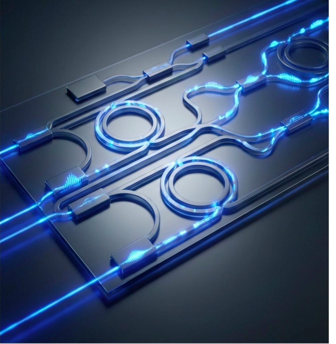
The silicon photonics supply chain is maturing rapidly - front-end PIC fabrication is increasingly available through dedicated foundries on 200 mm and 300 mm platforms. But every photonic IC requires backend wafer-level packaging to become a functional, integrable device.
That means dealing with wafer-level topography, managing thermal budgets around sensitive optical facets and waveguides, and placing bumps precisely in the laser cavity for hybrid III-V integration - all without degrading waveguide performance.
At Nanosystems JP Inc., we specialize in the post-CMOS wafer processes that PIC designers and fabless photonics companies need: through-silicon vias (TSV), redistribution layers (RDL), under-bump metallization (UBM), solder bumping, passivation, wafer bonding, DRIE cavity formation, and optical facet preparation.
We process both frontside and backside of photonic and CMOS/EIC die - including RDL and UBM on companion CMOS/EIC wafers for 2.5D and 3D co-packaged assemblies. All dielectric depositions use low-temperature PECVD (<200 °C) to protect waveguides, Ge photodetectors, and bonded III-V layers.
Carrier wafer bonding & debonding: For backside processing - thinning, TSV reveal, backside RDL, and backside UBM - we bond your device wafer face-down to a temporary carrier using thermal-release or UV-release adhesive. After all backside processes are complete, we debond the carrier cleanly with no residue on the device surface.
Flexible TSV integration: If your wafer arrives with blind TSVs already etched and filled (TSV-first or TSV-middle), we perform wafer thinning and Cu CMP to reveal the buried via tips, then continue with backside RDL, UBM, and bumping. If your wafer has no vias, we etch and fill new TSVs (TSV-last) after thinning. Either path delivers a complete backend packaging flow.
Typical Customer Profiles
- Fabless SiPho companies needing backend packaging after PIC tape-out at GF, TSMC, Tower, imec, or AMF
- PIC designers developing co-packaged optics (CPO) prototypes - frontside and backside processing on PIC and CMOS/EIC die
- Laser integration houses needing bumps in the laser cavity for hybrid III-V flip-chip bonding onto SiPho PICs
- Research institutes requiring custom TSV, RDL, or optical facet preparation on photonic wafers
- Telecom / datacom module houses integrating 400G-1.6T transceiver engines
- LiDAR, biosensor, and quantum photonics startups needing carrier-bonded backside processing flows
- OSATs seeking sub-contracted processes: AuSn bonding, DRIE cavities, UBM, low-temp PECVD passivation
As a pure-play foundry, we offer process flexibility with no minimum order quantity - from single-wafer engineering runs to production lots. Our Tokyo cleanroom handles wafers up to 200 mm (8″) with full backend process capability.
Wafer before & after
backend packaging
Your photonic wafer may arrive with blind TSVs already etched and filled (TSV-first or TSV-middle). We bond your device wafer to a carrier, backgrind, CMP reveal TSV tips, then add backside RDL, UBM, low-temperature PECVD passivation, and C4 solder bumps - then debond the carrier. For wafers without vias we etch and fill new TSVs (TSV-last).
Full backend wafer-level packaging -
every process, one project
All 15 backend processes available as a complete flow or as standalone services, managed as one project at Nanosystems JP Inc.
| Process | Specifications | Materials / Notes | Typical Application |
|---|---|---|---|
| Through-Silicon Via (TSV) | Dia. 5-100 µm; depth up to 300 µm; aspect ratio ≤ 10:1. Supports TSV-last (etch + fill from backside after thinning) and TSV-middle (etch + fill from frontside). Incoming wafers with pre-existing blind TSVs (TSV-first or TSV-middle) accepted for reveal + backside processing. | Cu fill (electroplated); SiO₂/Si₃N₄ isolation liner | 3D PIC-EIC stacking, vertical I/O, CPO optical engine |
| TSV Reveal (Backgrind + CMP) | Wafer thinning by backgrind to target thickness (typically 50-150 µm), followed by Cu CMP to expose buried TSV tips. Temporary carrier bonding / debonding included. Surface roughness < 1 nm Ra after CMP. | Temporary adhesive bond; CMP slurry matched to Cu/Si/oxide | Reveal blind TSVs; enable backside RDL and bumping |
| Redistribution Layer (RDL) | L/S ≥ 5/5 µm (single layer); up to 3 RDL layers. Cu or Al metallization. Frontside and backside RDL on both PIC and CMOS/EIC die. Topo-aware patterning for wafers with existing surface topography. | Polyimide or PBO dielectric; Cu seed + electroplate | Fan-out routing, pad relocation, PIC-EIC interposer routing |
| Under-Bump Metallization (UBM) | Ti/Ni/Au, Ti/Cu/Ni/Au, or Cr/Ni/Au stacks. Pad size ≥ 40 µm. Frontside & backside UBM on PIC and CMOS die. Fine-pitch UBM for bumps in the laser cavity (III-V hybrid integration). | Ni: 3-10 µm (electroless or plated); Au flash: 50-200 nm | Flip-chip UBM, laser attach pads, EIC die UBM |
| Solder Bumping (C4 / µBump) | Bump pitch ≥ 100 µm (C4); ≥ 40 µm (µ-bump). Height 20-80 µm. Bumps in the laser cavity supported for III-V laser die flip-chip bonding onto PIC. | SnAg, AuSn, In-based; plated or printed | Flip-chip attach, laser-to-PIC bonding, CPO engine assembly |
| Passivation | SiO₂, Si₃N₄, or polyimide. Thickness 0.5-5 µm. Via openings ≥ 10 µm. Low-temperature PECVD (<200 °C) - critical for preserving waveguide performance, Ge PD, and bonded III-V layers. | PECVD SiO₂/SiN (low-temp); spin-coat polyimide/PBO | Electrical isolation, moisture barrier, inter-layer dielectric |
| Wafer Bonding | Hybrid (Cu-Cu + oxide), eutectic (AuSn, CuSn), fusion, SAB, anodic. Alignment accuracy ≤ 1 µm (hybrid); temperature range RT-400 °C. | Alignment ≤ 1 µm; bond void area < 2% | PIC-EIC 3D integration, III-V bonding |
| Carrier Wafer Bonding & Debond | Temporary bonding of device wafer to carrier for backside processing (thinning, TSV reveal, backside RDL/UBM). Thermal-release or UV-release adhesive. Clean debond with no residue on device surface. | Glass or Si carrier; Brewer Science / TMAT adhesives | Enable frontside + backside dual-side processing flows |
| DRIE / ICP-RIE Etching | Si Bosch etch depth ≤ 500 µm; sidewall angle 89-90°. Cavity & trench formation. Optical facet preparation by DRIE for edge-coupled waveguides - smooth sidewall finish for low-loss butt coupling. | SF₆/C₄F₈ chemistry; SiO₂/metal hard masks | V-groove, optical facet, cavity for fiber alignment, edge coupling |
| Optical Facet Preparation | DRIE-based optical facet formation for edge-coupled PICs. Smooth sidewall (<5 nm RMS) for low insertion loss. AR coating deposition on facet by low-temperature PECVD or e-beam evaporation. | SiN or SiO₂/TiO₂ AR stack; facet angle control ±0.5° | Edge coupling, butt coupling to fiber arrays or laser die |
| Thin Film Deposition | Sputtering, PECVD, ALD. Metals (Ti, Cr, Ni, Cu, Au, Al) and dielectrics. Low-temperature PECVD (<200 °C) for SiO₂ and SiN on temperature-sensitive photonic wafers. Film uniformity ≤ ±3%. | Film stress control; topo-compatible step coverage | Seed layers, barriers, AR coatings, low-temp dielectric stacks |
| Photolithography | Contact / stepper / e-beam. Resolution ≥ 0.5 µm (stepper). Substrate up to 200 mm. Positive/negative resist; thick resist for plating molds. | Contact, proximity, projection | RDL patterning, UBM liftoff, bump mold definition |
| Electroplating | Cu, Ni, Au, Sn, SnAg. Thickness range 1-100 µm. Uniformity ≤ ±5%. DC, pulse, and pulse-reverse modes. | DC and pulse plating; fill chemistry optimization | TSV fill, bump formation, UBM build-up |
| CMP | Oxide CMP for planarization; Cu CMP for RDL and TSV reveal. Surface roughness < 1 nm Ra. Slurry selection per material; endpoint detection. | Cu / oxide / dielectric slurries | Planarization, bonding surface prep, TSV reveal |
| Dicing | Blade dicing, stealth laser dicing. Street width ≥ 50 µm. DAF compatible; chipping ≤ 10 µm. Preserves optical facets when used after DRIE facet prep. | Blade and stealth laser; DAF film | Die singulation, bar-level test prep |
Key parameters for your
photonic wafer backend layout
Contact us for a full DRM document tailored to your specific stack-up and wafer thickness.
TSV Design Rules
| Via diameter | 5-100 µm |
| Min. pitch (center-to-center) | 2× diameter |
| Max aspect ratio | 10:1 |
| Keep-out zone from waveguide | ≥ 50 µm * |
| Isolation liner | SiO₂ ≥ 200 nm |
| Cu fill void tolerance | <5% by X-ray |
| Supported TSV types | TSV-last, -middle, reveal |
| Reveal target thickness | 50-150 µm |
* Depends on waveguide type and optical mode confinement. Consult our engineers. Incoming wafers with blind TSVs (TSV-first / TSV-middle) accepted - we perform reveal + backside processing.
RDL Design Rules
| Min. line / space | 5 / 5 µm |
| Metal thickness (Cu) | 3-10 µm |
| Dielectric thickness | 5-15 µm (PI) |
| Via diameter (inter-layer) | ≥ 15 µm |
| Max RDL layers | 3 |
| Alignment accuracy | ≤ ±2 µm |
UBM & Bump Rules
| UBM pad opening | ≥ 40 µm |
| UBM stack (frontside) | Ti/Ni(5µm)/Au(50nm) |
| UBM stack (backside) | Ti/Ni/Au or Cr/Ni/Au |
| C4 bump pitch | ≥ 100 µm |
| µ-bump pitch | ≥ 40 µm |
| Bump height uniformity | ±5 µm (3σ) |
Passivation, Bonding & Carrier
| Passivation via opening | ≥ 10 µm |
| Passivation overlap on pad | ≥ 5 µm per side |
| Low-temp PECVD (SiO₂/SiN) | <200 °C |
| Bond alignment (hybrid) | ≤ 1 µm |
| Bond interface void area | <2% |
| Surface roughness (bond) | <0.5 nm RMS |
| Carrier adhesive type | Thermal- or UV-release |
| Thermal budget (PECVD) | ≤ 200 °C |
Two standard paths -
TSV reveal or TSV-last
Choose the path that matches your incoming wafer. Both deliver a fully packaged, flip-chip-ready photonic die.
Silicon photonics backend packaging spans
the fastest-growing segments in optoelectronics
Data Center Transceivers
400G / 800G / 1.6T pluggable and on-board optics. Flip-chip PIC-EIC integration with C4 or µ-bump interconnects for high-speed SerDes lanes and power delivery.
Co-Packaged Optics (CPO)
Optical engine packaging for next-gen AI switches and GPU clusters. TSV-based 3D stacking of photonic and electronic ICs on a common interposer for shortest electrical reach.
LiDAR & Autonomous Sensing
FMCW and ToF LiDAR photonic engines requiring compact wafer-level packaging, fiber-to-chip V-groove alignment, DRIE cavities, and rugged environmental sealing.
Telecom & 5G / 6G
Coherent transceiver PICs for metro / long-haul WDM networks. Backend packaging with tight thermal budget control for III-V heterogeneous integration and high-yield assembly.
Biosensors & Medical Photonics
Photonic biosensor chips with microfluidic integration. DRIE cavity formation for sample flow channels combined with optical waveguide sensing structures.
Quantum Photonics
Integrated quantum photonic circuits requiring ultra-clean wafer bonding, low-loss waveguide-compatible backend processing, and cryogenic-grade metallization stacks.
Built for photonics backend -
not adapted from CMOS packaging
All Backend Processes Coordinated
TSV, TSV reveal, RDL, UBM, bumping, passivation, carrier bonding/debonding, optical facet prep, wafer bonding, DRIE, CMP, dicing - all managed as one project at Nanosystems JP Inc. Frontside and backside processing on both PIC and CMOS/EIC die.
No Minimum Order Quantity
We run single-wafer engineering lots through to production volumes. Ideal for prototyping and process development before committing to high-volume OSAT flows - no MOQ, no minimum lot charge.
Process Flexibility
Bumps in the laser cavity, non-standard UBM stacks, custom DRIE optical facets, topo-aware RDL on wafers with existing surface topography. We build custom process flows for photonic IC requirements, not cookie-cutter packages.
Low-Temperature Processing
All dielectric depositions available at low-temperature PECVD (<200 °C). We understand that photonic waveguides, Ge photodetectors, and bonded III-V layers have strict thermal budgets - every process step is designed to stay within your allowed temperature envelope.
Japan Quality, Global Reach
Tokyo-based cleanroom with Japanese manufacturing discipline. Extensive experience serving customers in the US, Europe, and across Asia with English-language technical communication and NDA-protected engagement.
Fast Turnaround
Typical lead time of 8-11 weeks from design finalization to wafer shipment. Expedited schedules available for critical-path prototyping runs. Response to RFQ within one business day.
Dedicated pages that start from this process
SiN and SOI waveguides, gratings, resonators and couplers from your GDS, before packaging.
Ready to package your photonic IC?
Initial response within one business day.
Share your process requirements, substrate, and production volume. A Nanosystems JP Inc. engineer will give an initial response within one business day. Full quote typically within 7-10 business days, subject to project complexity and NDA requirements.